How we do
To develop our network we follow step by step process to keep our quality and standard of work. All works are properly QC by our expert engineers and we deliver our client quality service with updated devices from Brand Vendors.
To establish underground backbone network we go through following steps:
1. Route Survey and design
2. Preparation of BOQ
3. RoW Permissions
4. Trenching, ducting and backfilling
5. Aerial Cabling
6. Supply of Materials
7. Horizontal Directional Drilling
8. Cable blowing / pulling
9. Duct integrity test
10. Optical Fiber Cable blowing
11. Fusion Splicing
12. Fiber Termination
13. End to End Link Testing
Access Network Development
1. Survey and Digitized Maps For Proposed Routes
2. Route Survey
3. RoW Permissions
4. Trenching, ducting and backfilling
5. Cable pulling / blowing
6. Splicing
7. Aerial Cabling
8. Distribution Box Installation
9. Cable Testing
Route Survey & Design
The entire route is surveyed for laying of Optical Fiber Cables for the following inputs:
1. RoW demarcation
2. Soil strata
3. Existing Underground utilities
4. Road / Rail / Bridge / River / Canal Crossings
5. BOQ Estimation
6. Any other criticalities

BOQ Estimation and approval from Customer
On the basis of survey details an estimated BOQ is prepared and submitted to get the approval from the Customer.
Supply of Materials
We supply the following material required for construction of Backbone Network.
1. HDPE Ducts
2. Optical Fiber Cable
3. Fiber Joint Closures
4. Pre cast Chambers
5. Route Markers etc.
Right of Way Permissions
A Single Line Diagram is made, to determine jurisdictions for the statutory permissions such as
1. Roads and Highways
2. Railway Department
3. Roads & Buildings Department
4. Municipal corporations
5. Irrigation department
6. National highway Authorities etc.
7. Cantonments
Applications are submitted on behalf of the client, to each of the departments involved, and necessary permissions obtained after making payments as applicable (by the client)
Trenching, ducting and backfilling
Excavation of Trenches Standard depth of trench will be as per specifications, outside the city limits trench will normally follow boundary of roadside land. However, where road side land is full of borrow pits or forestation, or when cable is to be laid along Culverts/bridges or cross-streams, trench may be
made closer to road edge or in some cases, over embankment or shoulder of the road.
Line up of trench would be such that HDPE duct(s) will be laid in straight line, both laterally as well as vertically except at locations where it has to necessarily take a bend because of change in alignment or gradient of trench. Minimum radius of two meters will be maintained, where bends are necessitated.
Duct Laying
Ducts will be laid in a flat bottom trench, free from stones, and sharp edged debris. The duct would be placed in trench as straight as possible, however at bends horizontal and vertical minimum bending radius for duct would be maintained as per advised specifications.

Ducts will be laid preferably using dispenser designed for it. Our supervisor will ensure that Duct laid is free from twist and collapsed portion of Ducts. Any such portion will be rectified before backfilling by using couplers. Ends of ducts will always be closed with END PLUGS to avoid ingress of mud, water or dust. We ensure HDPE ducts are clear of sand, dust or any other particles, which would cause obstruction in lying of cable. Prior to aligning the ducts for jointing, each length of the HDPE ducts will be thoroughly cleaned to remove all sand, dust or any other debris that may clog, disturb or damage the
optical fiber cable when it is pulled or blown at a later stage.
The ducts will be joined with couplers using duct cutter & other tools and will be tightened and secured properly. The duct joint will be practically airtight to ensure smooth cable blowing using cable blowing machines.
Laying of Gl and / or RCC pipes as additional protection for the HDPE ducts at rail / road crossings, built-up area/city limits, on culverts and bridges will be done as required. Chambering or concreting around RCC/ Gl pipes as additional protection on bridges, culverts and also on stretches wherever depth of excavation is less than specified will be done. Reinstatement of excavated trench will be done with proper compaction.
Crowning When backfilling has been done up to ground level a hump of soil is made to cater for soil settlement. Entire excavated soil will be used for back filling. Crowning will be confined over width of trench only.
Duct Integrity Test
After backfilling ducts shall be tested for integrity (air tightness and kink-free shape). Air tightness test is done by pressurizing 2 km duct stretches at a time. One end of duct will be closed and compressed air at 5-6kg/cm2 is sent from the other end. At about 5kg/cm2 pressure the inlet of compressed air will be closed. Fall in pressure should not be more than 50% in 1(one) hour.
To check that duct has not collapsed or kinked a wooden cylindrical piece (shuttle) is blown into the duct with far end fitted with Flexible wire grip/stocking. The wooden shuttle should pass through duct at far end without any obstruction and within approx. 10 minutes or less.
Fiber Termination All fibers of OF cables will be terminated on Fiber Management System (FMS) at each regenerator (REG) or ADM (add drop multiplexer) location.
Installation of FMS is done according to the manufacturer's specification. End to End testing can be carried out from the FMS to FMS using the connectors who are mounted on the FMS.
Survey and Digitized Maps
The survey digitized maps will have the following information:
1. Relative position of proposed OFC route with respect to existing cables.
2. Marking of Rocky, Submerged and Normal soil terrain.
3. Marking of Crossing locations and type of proposed crossing detail viz.
4. HDD, Open cut, and Boring etc.
5. Marking of offset availability.
6. Geographical co-ordinates for all crossing HDPE duct coupling and OFC jointing locations.
7. Assessment of required materials.
8. Identifying Critical points.
9. Demarcation of RoW.
Cable Testing
The Cable will be tested before pulling/blowing to ensure continuity also to evaluate the losses if any.
Aerial Cabling At places where open trenching is not possible due to very narrow roads and due to delay in obtaining Row, this method will be adopted as a temporary solution. Also by using special cables (ADSS) this will be laid along the Transmission lines for longer distances.
Distribution Boxes The distribution boxes will be positioned at every location where a main cable will be distributed to sub - areas with lesser pair cables.
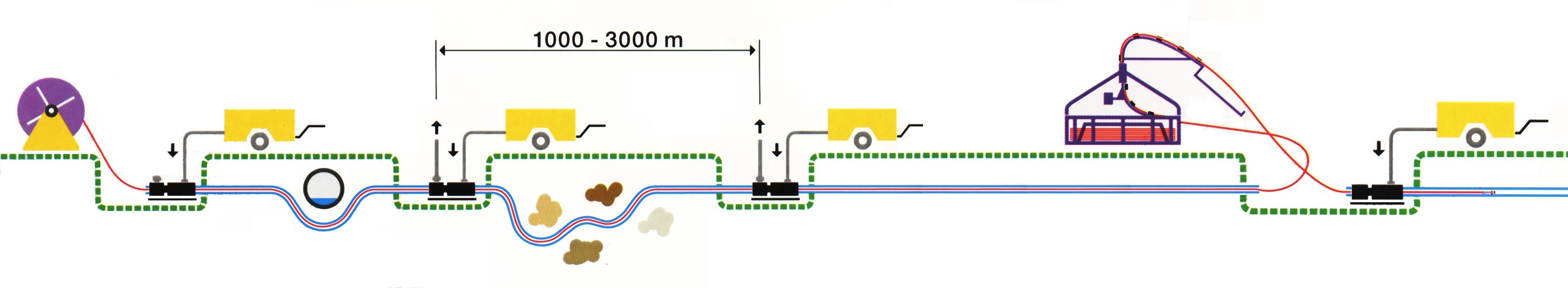
Cable blowing Cable blowing machine (Cable jet or any other machine) would be deployed along with a good compressor.
Cable drum will be loaded on payoff stand & unwound from topside of the drum. Pay off stand would be placed properly so that it does not collapsed while dispensing OFC.
Fusion Splicing
Splicing is done using a good quality splicing machine. Splice loss per joint will be minimum and would not be more than 0.07 dB. In no case average splice loss per link will be more than 0.06 dB x No. of splices. At least 0.6 M to 0.8 M fiber would be stored in cable tray. Fiber would be neatly coiled without kinks. Minimum bending radius of 80mm would be ensured, Joint closure would be sealed properly before it is taken out of the controlled environment free from dust particles and air-conditioned splicing van.

End to End Link Testing
Link Test is carried out on entire section terminated at both ends after completion of tasks to ensure the losses are within permissible limits on all fibers.
Horizontal Directional Drilling
This technique is adopted wherever open trenching cannot be made due to congestion.